What is a Construction Drawing?
A construction drawing is like a map or blueprint that tells builders how to construct a building or structure. It shows all the important details, measurements, and materials needed for the construction project.
Mastering Construction Drawing
Think of it as a step-by-step guide that helps everyone involved in the construction understand what needs to be done and how to do it.
It’s like a visual plan that ensures everyone is on the same page and can work together to bring the project to life.
Mastering Construction Drawing
Architectural drawings in the design process
Architectural drawings are important tools used in the design process of buildings and structures.
They are like visual representations or sketches that architects create to communicate their ideas and concepts.
These drawings help architects and their clients visualize and understand what the final design will look like.
There are different types of architectural drawings that serve specific purposes.
Floor plans show the layout of rooms and spaces from a bird’s-eye view, while elevations provide a side view of the building’s exterior.
Sections show a cut-through view of the building, revealing its internal structure. Additionally, architects may create perspective drawings or 3D renderings to give a realistic representation of how the building will appear.
Architectural drawings are not only used to convey the aesthetics of a design but also to communicate technical details.
They include dimensions, materials, and specifications, enabling builders and contractors to understand how to construct the building accurately.
Overall, architectural drawings are essential in the design process as they help architects, clients, and construction teams visualize, communicate, and bring the architectural vision to life.
What are Construction Drawings?
Mastering Construction Drawing
Construction drawings are like detailed maps or instructions that tell builders how to construct a building or structure.
They are created by architects, engineers, or drafters and serve as a guide for the construction process.
These drawings show all the important details, measurements, and specifications needed to build the project.
They include information about the layout of rooms, the placement of walls, doors, and windows, and the materials to be used.
Construction drawings also indicate the electrical and plumbing systems, as well as any structural elements.
Builders use these drawings to understand how to build the project correctly and ensure that all the different parts fit together properly.
They follow the instructions provided in the construction drawings to carry out the construction work accurately.
In simple terms, construction drawings are like step-by-step instructions that show builders exactly what needs to be done and how to do it.
They play a crucial role in ensuring that the building or structure is constructed according to the design plans and specifications.
What is included in a set of architectural construction drawings?
A set of architectural construction drawings includes several important elements and information necessary for building a structure. Here are some key components typically found in such a set:
- Floor Plans: These drawings show the layout of each floor, including walls, rooms, and spaces. They provide a bird’s-eye view of the building, indicating the dimensions and arrangement of various areas.
- Elevations: Elevations are like side views of the building, showing its exterior appearance. They depict the height, shape, and design of the building’s façade, including windows, doors, and other architectural features.
- Sections: Sections are cut-through views of the building that reveal its internal structure. They show details such as wall thickness, ceiling height, and the relationship between different floors.
- Site Plan: This drawing displays the building’s location on the site and includes information about the surrounding environment, topography, and any landscaping or external structures.
- Details: Details drawings provide close-up views of specific building elements or construction methods. They illustrate how different components, such as windows, doors, or stairs, are assembled and connected.
- Structural Drawings: These drawings depict the structural elements of the building, such as columns, beams, and foundations. They provide information on how the building will be supported and constructed to ensure stability and safety.
- Electrical and Plumbing Plans: These drawings illustrate the layout and placement of electrical and plumbing systems throughout the building. They include information on wiring, outlets, fixtures, and pipelines.
- Schedules and Specifications: Schedules outline the materials, finishes, and fixtures to be used in the construction, while specifications provide detailed instructions and standards for construction methods and materials.
In summary, a set of architectural construction drawings includes floor plans, elevations, sections, site plans, details, structural drawings, electrical and plumbing plans, as well as schedules and specifications. These drawings collectively provide a comprehensive guide for builders to construct the building accurately and in accordance with the design intent.
Mastering Construction Drawing
Other drawings include (depending on the project)
Other drawings that may be included in a set of architectural construction drawings, depending on the project, are:
Mastering Construction Drawing
- Landscape Plans: These drawings outline the design and placement of landscaping elements such as plants, trees, pathways, and outdoor amenities.
- Interior Design Plans: These drawings focus on the interior spaces of the building, showing the arrangement of furniture, fixtures, and decorative elements.
- Mechanical Drawings: Mechanical drawings provide details about the heating, ventilation, and air conditioning (HVAC) systems, including ductwork and equipment placement.
- Fire Protection Drawings: These drawings indicate the location and design of fire suppression systems, such as fire sprinklers and fire alarm systems.
- Accessibility Drawings: These drawings highlight features that ensure accessibility for people with disabilities, such as ramps, elevators, and accessible restrooms.
- Millwork and Cabinetry Drawings: These drawings provide detailed plans for custom-built elements, such as cabinets, shelves, and built-in furniture.
- Roof Plans: Roof plans depict the design and layout of the roof, including slopes, drainage systems, and any rooftop equipment.
- Demolition Plans: In renovation projects, demolition plans show which parts of the existing structure need to be removed or altered.
These additional drawings cater to specific aspects of the project and provide detailed instructions and specifications for their respective areas.
They contribute to a more comprehensive understanding of the building design and construction requirements.
What information is in a construction drawing?
Construction drawings contain important information that guides builders in the construction process. Here are the key details typically found in construction drawings, explained in simple terms:
- Dimensions: Construction drawings provide measurements and dimensions for each component of the building, such as walls, rooms, and structural elements. This ensures accurate placement and sizing during construction.
- Symbols and Labels: Various symbols and labels are used to represent different elements, such as doors, windows, plumbing fixtures, and electrical outlets. These symbols help builders identify and correctly install each item.
- Materials and Finishes: Construction drawings specify the materials and finishes to be used for different parts of the building. This includes details about the type of flooring, wall coverings, roofing materials, and other finishes.
- Construction Techniques: Drawings may include specific instructions on how to construct certain elements. For example, they may show the proper techniques for framing walls, installing windows, or laying bricks.
- Structural Information: Construction drawings provide details about the building’s structural components, including beams, columns, and foundations. They indicate their size, placement, and connection methods to ensure stability and safety.
- Plumbing and Electrical Layout: Drawings show the layout of plumbing and electrical systems, indicating the location of pipes, wires, fixtures, and outlets. This helps builders install these systems correctly.
- Notes and Specifications: Important notes and specifications are included to provide additional instructions or guidelines. These may include details about specific building codes, safety requirements, or construction methods to be followed.
- Schedules and Lists: Construction drawings may include schedules or lists that outline the quantities and specifications of materials, equipment, or fixtures needed for the project.
By providing this information, construction drawings serve as a comprehensive guide that allows builders to understand the design intent and construct the building accurately and efficiently.
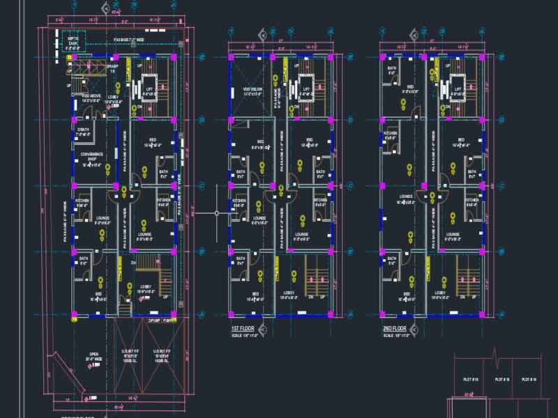
Floor Plan Construction Drawing
Mastering Construction Drawing
A floor plan construction drawing is a specific type of construction drawing that focuses on illustrating the layout and dimensions of each floor of a building. It provides essential details about the spatial organization and features of the building’s interior. Here are some key details typically included in a floor plan construction drawing:
- Room Layout: The floor plan shows the arrangement and sizes of rooms, including bedrooms, living areas, kitchens, bathrooms, and other spaces within the building. Each room is typically labeled and may include dimensions indicating its length, width, and area.
- Walls and Partitions: The drawing outlines the locations and dimensions of walls and partitions that divide the different rooms and areas. It indicates the thickness of walls and may include symbols to represent different types of walls (e.g., load-bearing, non-load-bearing).
- Doors and Windows: The position, size, and swing direction of doors and windows are specified in the floor plan. Symbols or annotations are used to indicate the type of door (e.g., hinged, sliding) and the type of window (e.g., casement, double-hung).
- Circulation and Pathways: The floor plan shows the arrangement of corridors, hallways, staircases, and other circulation paths within the building. It illustrates how people can move through the different areas of the floor.
- Structural Elements: The drawing may include basic structural elements, such as columns or load-bearing walls, if they impact the floor plan layout. This provides an understanding of the building’s structural support.
- Fixtures and Fittings: The floor plan may include symbols or labels for fixtures and fittings, such as sinks, toilets, appliances, and built-in furniture. These elements help builders understand their specific locations and requirements.
- Dimensional Information: Measurements and dimensions are typically included in the floor plan drawing. They indicate the distances between walls, the length and width of rooms, and the overall dimensions of the floor.
- Scale and Orientation: The floor plan is drawn to a specific scale, which allows builders to accurately interpret the sizes and proportions of the spaces. The drawing also indicates the compass orientation (north direction) for reference.
Floor plan construction drawings serve as a visual representation of the building’s interior layout, helping builders understand the organization of spaces and accurately construct each floor according to the design intent.
Mastering Construction Drawing
Elevation Construction Drawing
Elevation construction drawing: Understanding its purpose and components
An elevation construction drawing is a vital component of architectural design that provides a detailed visual representation of a building’s exterior appearance. It offers a vertical view of the building’s façade from different angles, showcasing its height, proportions, and architectural features. Here’s an overview of the purpose and key elements found in an elevation construction drawing:
Purpose: Elevation drawings serve multiple purposes in the construction process. They help architects, builders, and clients visualize the building’s exterior design and ensure that the intended aesthetics are accurately translated into the final structure. These drawings are crucial for communicating design intent, coordinating with various stakeholders, and guiding the construction team during the building process.
Components:
- Building Facade: Elevation drawings showcase the building’s exterior walls, including their height, width, and surface finishes. They provide a clear representation of the building’s shape and overall appearance from a particular vantage point.
- Doors and Windows: Elevation drawings depict the placement, size, and style of doors and windows on the building’s façade. These details ensure that the openings are appropriately positioned and proportioned to achieve a balanced and visually appealing design.
- Architectural Features: Elevation drawings illustrate any distinctive architectural elements, such as columns, cornices, balconies, or decorative accents. These features are essential for conveying the building’s style and character.
- Material Indications: Elevation drawings may include indications of the materials to be used on the building’s exterior, such as brick, stone, stucco, or siding. This information helps builders understand the desired material finishes and textures.
- Roof Design: The drawings may show the shape, slope, and overhangs of the roof. They communicate important details about the roof’s profile and materials, contributing to the building’s overall aesthetics and functionality.
- Scale and Measurements: Elevation drawings are typically drawn to scale, allowing viewers to understand the proportions and dimensions of the building accurately. Measurements may be provided to indicate the height and widths of various elements.
- Notations and Annotations: Elevation drawings may include annotations, symbols, or text to provide additional information about specific design features, materials, or construction details. These annotations clarify important aspects of the building’s façade and aid in the construction process.
Elevation construction drawings play a crucial role in visualizing and communicating the exterior design of a building. By providing detailed representations of the building’s façade, including architectural features, doors, windows, and materials, these drawings ensure that the construction team can accurately execute the intended design vision.
Mastering Construction Drawing
Quick Links
Social Icons
Contact Us Information
443 J3 Johar Town Lahore near Expo Center Lahore